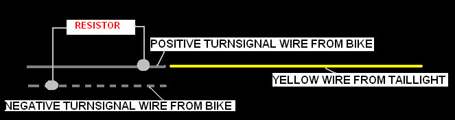
Connect the
yellow wires to the positive turn signal wires using provided red connectors
or alternately use your existing factory connectors.
Ground wire is
not needed unless you are using resistors to slow down the blink rate. (The ground wire is the same color wire used on both turn
signals). To slow down the blinking rate use provided resistors. Connect one end of resistor to the yellow wire and the other end of resistor
to the negative turn signal wire.
Note:
You can use an electrical variable load flasher. These flashers are
sold for $9.99. Click here for instructions on how to install.
Resistors are not needed if you choose to use the
variable load flashers.
Problem: The unit is not working, I get
no power (Running light nor the brake light comes on)
Solution: Check to make sure
connector is properly connected. Make sure the pins inside the
connector is pushed up to the top
of the connector. The pins inside the connector must make
contact with the pins inside your factory connector.
Soluton: Check to make sure the metal pin inside the
connector is crimped through the plastic covering over the black wire.
Problem: My turn signals stay on and do
not blink.
Solution: Either your front signals
have been changed, removed, or disconnected. If so, the resistor is
needed.
Problem: My turn signal on one side stays lit all
the time.
Solution: You have connected the turn signal to your
license plate light connector.
Solution: Use the provided resistors
Problem: My turn signals seem dim
Solution: Check and make sure you connected the turn
signal wires to the positive and not the ground wires.
Problem: My running light works but my
brake light does work.
Solution: Check and make sure that
the metal pin inside the connector is crimped through the plastic covering
over the green wire.
Problem: My brake light works but my running light
does not work.
Solution: Check and make sure that the metal pin inside
the connector is crimped through the plastic covering over the red wire.
Problem: My turn signals blink too fast.
Solution: Either replace your
flasher unit w/ a variable load flasher or use the provided resistors.
Click here for instructions on how to install.
Problem: The resistors heat up.
Solution: Resistors will generate
heat as it is designed to replace your bulbs. We recommend you mount
away from any plastic
or painted surfaces.
Problem: My turn signals do not cancel my
running/brake light when my brakes are applied.
Solution: This may be the case for Kawasaki's. We
recommend that you change the flasher unit with a
Variable Load flasher. These can be found at any local auto parts
stores and cost about $2.00. The flasher is located on
left side underneath the seat.
Click here for instructions on how to install.
Some simple problems may occur on Honda's from
year 2000-2005. These problems may include the following:
1. My fuses keep blowing
2. One side of the taillight does not work
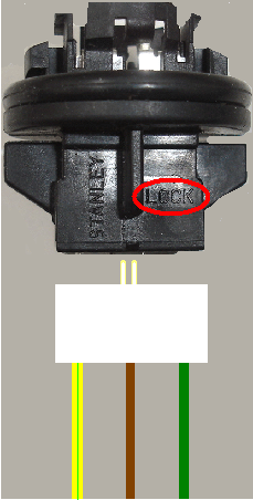
Solution: Please check the wiring
connection on the bulb socket (Black piece that your bulbs plug into).
This piece has a white connector that plugs into the back. There are 3
wires that go into the white connector; Yellow/green stripe - Running
wire, Brown wire - ground wire, Green wire - brake wire. Make sure the
white connector plugs into the black socket with the green wire facing the
same side as the work "LOCK" (Pictured with a red circle).
Make sure both connectors (right side and left side) are connected the same.
After this procedure, plug in our taillight and start the bike. If the
light does not illuminate or only one side illuminates, just un-plug our
connector, turn the connector 180 degrees and try again.
Please note. You can perform a diagnostic test for
the turn signals. Plug in the unit and touch each yellow wire with a
power source. If the turn signals activate (by staying lit) then the
unit is fine.